ThermTrac
Features
- Up to 165 W/m
- Tmax maintain 200°C
- Up to 5 kV
Application
A Thermon ThermTrac system provides a cost-effective alternative to conventional resistance heat tracing on long pipelines by eliminating the need for an extensive power distribution system. A pipeline up to 25 kilometers long can be traced from a single power point. The versatility of the system makes it ideal for temperature maintenance, freeze protection and heat-up applications.
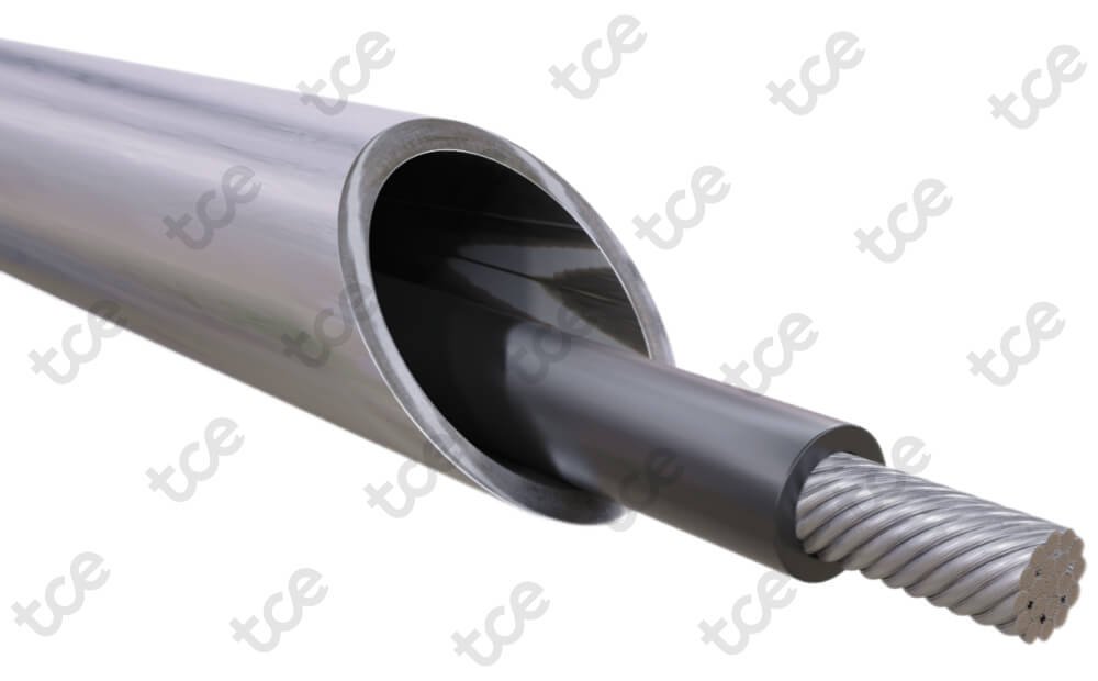
The system generates heat in the heat tube by the return electrical current flowing through the impedance of the inner skin of the heat tube. There is no voltage or current on the outer skin of the heat tube. The ThermTrac insulated conductor is the heart of Thermon’s skin effect heating system. This conductor is custom designed by Thermon with dielectric insulation and optional scuff jacket to meet specific project applications. ThermTrac insulated conductor is manufactured 100% by Thermon so the highest quality can be obtained.
ThermTrac systems are approved for use in ordinary (nonclassified) and hazardous (classified) areas.
Typical ThermTrac system
ThermTrac power connection, pull/splice, and end termination boxes are integral to the skin effect heating system and carry current in the same manner as the heat tube. These boxes are constructed of heavy wall ferromagnetic materials and must be welded to the heat tube to ensure the continuity of the skin effect electrical path. The boxes are constructed to conform to the carrier pipe and provide water-resistant protection with gasketed, bolted covers.
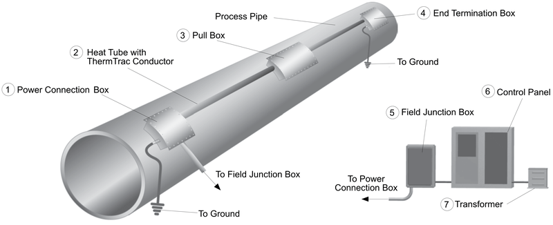
- Power connection box: Located at the power feed end of the ThermTrac circuit, the power connection box permits the connections that supply electrical energy to the system. An external tab on the box permits grounding of the system.
- Ferromagnetic heat tube: Used to produce heat based on the two phenomena of proximity effect and skin effect.
- Pull box: Located periodically along the heat-traced pipe, this box permits access for installing the ThermTrac conductor. The box is sized to provide for expansion/contraction of the conductor, and versions of the box allow the heat tube to cross over the carrier pipe if necessary at elevation or directional change points.
- End termination box: The design and construction of the end termination box allows the ThermTrac conductor and heat tube to be joined together thereby allowing electrical current to return to the power connection box via the inside surface of the heat tube. An external tab on the box permits grounding of the system.
- Field junction box: Located between the Power Connection and the Load Center it provides an access point to terminate the ThermTrac conductor and the power feed wiring.
- Control panel: Typically consists of all electrical power, control and monitoring devices.
- Transformer: Custom transformer equipped with over and under voltage taps.
Features
- Freeze protection and temperature maintenance up to 200°C
- Maximum exposure temperature 260°C
- Power outputs up to 165 W/m
- Operating voltages up to 5 kV
- Circuit lengths up to 24 kilometers
- Nickel-plated copper bus wires
- Rugged heat tube to generate heat
- Available scuff jacket
- Worldwide approvals
Resources
Datasheet
English (Europe) datasheet
English (Americas) datasheet
Sales brochure
English (Americas) sales brochure
Specifications
General
- Manufacturer
- Thermon
Ratings
- System operating voltages
- Up to 5 kV (TT-XR) and up to 3.5 kV (TT-HT)
- Maximum maintain temperature
- 110°C TT-XR and 200°C TT-HT
- Maximum continuous exposure temperature
- 150°C TT-XR and 260°C TT-HT
- Minimum installation temperature
- Down to -40°C
- Minimum bend radius
- 6x cable O.D.
- T-rating
- T6 to T2