Application overview
Control and monitoring systems can play an essential role in heat tracing applications which range from freeze protecting water lines to maintaining elevated process temperatures. While mechanical thermostats have been used successfully for many heat tracing applications, a more complete control and monitoring solution can be necessary for critical heat tracing applications. Advancements in technology have made electronic control and monitoring units both cost effective and more reliable. These systems conserve energy, extend system life, and ensure accurate temperatures are maintained, for reduced operating cost and increased plant reliability.
The Genesis Controller's key features include:
- Monitor electric heat trace circuit load currents
- Selectable control methods (On/Off, On/Off with Soft Start, Proportional, Ambient Proportional) for each individual circuit
- Programmable alarm set points, with time delay and remote alarm acknowledgment and reset capabilities
- Programmable "trip" set-points for each circuit
- Temperature sensor status indication
- Unique circuit identifier (48 characters maximum)
- Communication to host computer via Ethernet communications
- Adjustable ground/earth leakage "trip" and/or alarm capabilities
- Addressable RTD Temperature Sensors - up to twenty (20) per circuit
- Up to 6 months history to aid in troubleshooting
- ISO drawing in png format for viewing on Genesis HMI
System components
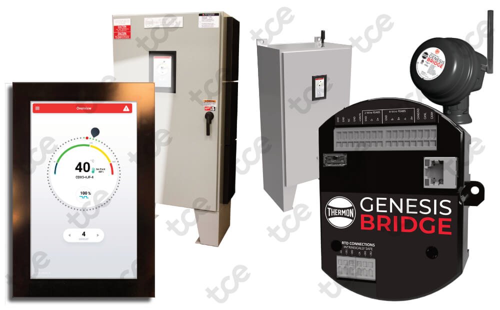
The Thermon Genesis system consists of various components which together form a complete control and monitoring solution.
HMI (HUMAN MACHINE INTERFACE)
The HMI serves as the central monitoring and interrogation point for a Genesis Controller system, including its heat tracing control modules. Through its touch screen monitor, the HMI allows the operator to access operating control parameters and operating conditions throughout the heat tracing system network. The HMI communicates directly with the Genesis Network and DCS systems through its Ethernet port.
DCM (DISTRIBUTED CONTROL MODULE)
The DCM serves as the power switching module, using solid state relays for a network of heat tracing control modules.
DTM (DISTRIBUTED TEMPERATURE MODULE)
The DTM is a DIN rail mountable six RTD sensor input module which links the field RTD wiring to the DCM module via CANBus. Any RTD sensor may be mapped to any heater circuit on the CANBus network.
IOM (INPUT OUTPUT MODULE)
The IOM is a DIN rail mountable input/output module with 6 individually configurable input/output channels and one dedicated system fault alarm output. Outputs may be configured to signal a variety of conditions such as trips, low temperature alarms, ground/earth leakage alarms, etc. Inputs may be used to trigger a variety of events such as load shed or forcing on circuits.
GENESIS NETWORK
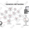
The Thermon Genesis™ Network consists of a control room server, a gateway, and a collection of field deployed bridges/nodes that form a wireless mesh communications network. Alternatively, the network can be made via a traditional wired Ethernet network. The Genesis™ Network connects all heat trace panels and controllers to the control room and gives visibility of all assets from a single dashboard and user interface that can be accessed from any browser. In addition to the Genesis Controller, the components of the Genesis Network Include:
• Thermon Genesis Bridge – node for wireless mesh communications
• Thermon Genesis Gateway – access point to/from the control room
• Thermon Genesis Server – supervisory and data analytics software
DCS (DISTRIBUTED CONTROL SYSTEMS) COMMUNICATIONS
Genesis Controller Systems communicate via Ethernet to the plant DCS. The same operating data and control capabilities that are available through the Genesis Network are also accessible in the plant control room at the DCS.
| SKU | P/N | Item | Product group |
|---|---|---|---|
| TMN.A20.043 | 810405 | HMI Assembly | Genesis controller for panel installation |
| TMN.A20.044 | 81050 | DCM Heat Sink | Genesis controller for panel installation |
| TMN.A20.045 | 810500 | DCM PCBA | Genesis controller for panel installation |
| TMN.A20.046 | 810505 | DCM Heat Sink Assembly | Genesis controller for panel installation |
| TMN.A20.047 | 81052 | Hardware Kit HS | Genesis controller for panel installation |
| TMN.A20.048 | 81055 | DCM Mechanical Relay | Genesis controller for panel installation |
| TMN.A20.049 | 810575 | DCM Assembly with Mounting Plate | Genesis controller for panel installation |
| TMN.A20.050 | 810605 | DTM6 Kitted Assembly | Genesis controller for panel installation |
| TMN.A20.051 | 810705 | IOM Kitted Assembly | Genesis controller for panel installation |
| TMN.A20.052 | 23850 | GN-B-XP | Genesis network |
| TMN.A20.053 | 23851 | GN-B-WP | Genesis network |
| TMN.A20.054 | 23852 | GN-B-A-XP | Genesis network |
| TMN.A20.055 | 23853 | GN-B-A-WP | Genesis network |
| TMN.A20.056 | 23854 | GN-B-A | Genesis network |
| TMN.A20.057 | 23855 | GN-GW | Genesis network |
| TMN.A20.058 | 23856 | GN-GAK-HAZ | Genesis network |
| TMN.A20.059 | 23857 | GN-GAK-ORD | Genesis network |
| TMN.A20.060 | S1057 | GN-SVR-BASE | Genesis network |
| TMN.A20.061 | S1058 | GN-SVR-BRDG | Genesis network |
Resources
Datasheet
English (Europe) datasheet Genesis Gateway
English (Europe) datasheet Genesis HMI
English (Europe) datasheet Genesis Bridge
English (Americas) datasheet Genesis Controller
Frequently asked questions
English (Americas) frequently asked questions TraceNet Genesis
Installation manual
English (Europe) installation instructions Genesis Controller
English (Europe) installation instructions TraceNet Genesis
Quick start
English (Europe) quick start guide Genesis
Certifications/Approvals
Genesis controller system
ETL Intertek
Nonhazardous Locations
ETL Listed Conforms to: UL STD. 508A
Certified to: CSA STD. C22.2 NO. 14
Hazardous Locations (Purge)
ETL Listed Conforms to: UL STD. 508A. NFPA STD. 496
Certified to: CSA STD. C22.2 NO. 14
Hazardous Locations
ETL Listed Conforms to: UL STD. 508A. UL STD. 12.12.01
Certified to: CSA STD. C22.2 NO. 14. CSA STD. C22.2 NO. 213
Genesis controller component
Genesis Controller components are certified for nonhazardous locations, hazardous locations, and Purge for hazardous locations.
IEC/EN/UL/CSA 61010-1
Ex ec IIC T4 Gc; II 3 Ex ec IIC T4 Gc
Class I, Division 2, Groups ABCD T4; Class I, Zone 2 Group IIC T4
Specifications
General
- Manufacturer
- Thermon
- Unit of measurement
- Piece


